

The contrast ratio of commercially available monitors is somewhere between 100:1 and 1000:1 - paper is even worse in this respect. This is by far lower than the contrast ratios of many real scenes which can easily reach 10,000:1 to 1,000,000:1. If an HDR image is composed from an exposure series properly capturing the full dynamic range of the scene this means that the HDR image can not be reproduced in a natural way on a normal monitor. As a consequence the dynamic range of an HDR image must somehow be mapped to the limited range of a monitor. This process is called 'tone mapping'.
Doing this 'tone mapping' in a simple manner would loose the natural contrast and details of a scene - the resulting image would look flat and dull. In the recent past many different tone mapping algorithms were invented because it turned out that developing a method that produces fine looking results for all thinkable types of scenes is not easy.
Tone mappers can be categorised into 'global' and 'local' acting methods. Global tone mappers work in a rather simple and computational efficient way. The resulting tonal value of a pixel is computed by applying a 'global' formula. In contrast local tone mappers handle each pixel by looking at surrounding pixels. This is computationally more expensive but in general produces better results in terms of local contrast and detail reproduction. Local tone mapping algorithms usually also allow for more influence on the "look" of the tone mapped result.
Usually the goal of tone mapping is to produce a natural looking LDR (low dynamic range) image from an HDR image that may be displayed on LDR media. However, tone mapping algorithms - and here especially local tone mappers - like other forms of digital image manipulation also allow for "creative" manipulation of HDR images resulting in quite expressive looking results. When exaggerated, tone mapping can even produce unsightly results. The following figure shows a scene that has been tone mapped in two ways: while the image to the left looks quite natural the right hand side image creates a dramatising effect.
|
|
|||
| Natural vs. dramatising tone mapping | ||||
HDR imaging and tone mapping techniques are especially important in panorama photography. This is because the large field of view captured in a panorama often results in huge intensity differences caused by strong light sources (e.g. sun) in the scene. As a consequence the captured scene becomes a HDR scene and should be handled accordingly. When tone mapping a panorama with a local tone mapping algorithm the projection of the panorama should be taken into account in order to avoid wrong results at the horizontal and vertical boundaries.
FDRTools implements four differing tone mapping methods.
Three of them are global methods and one is a local acting method named Compressor. While the global methods allow for basic tone mapping only the local Compressor algorithm is a capable and flexible tone mapper producing images with remarkable local contrast and fine detail.
You can switch between the methods by choosing the tabs Identity, Simplex, Receptor, or Compressor in the "Tone Mapping" module.
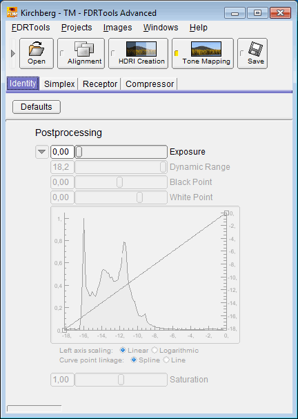
Identity does an identity mapping. This means the HDR image is mapped to itself. One may ask what could be the use of such a method. Well, Identity is used to display and inspect the HDR image. While Identity has all the controls of the Simplex method only one slider is active. However, displaying the other controls makes clear how Identity differs from Simplex.
 |
||
| The Identity dialog |
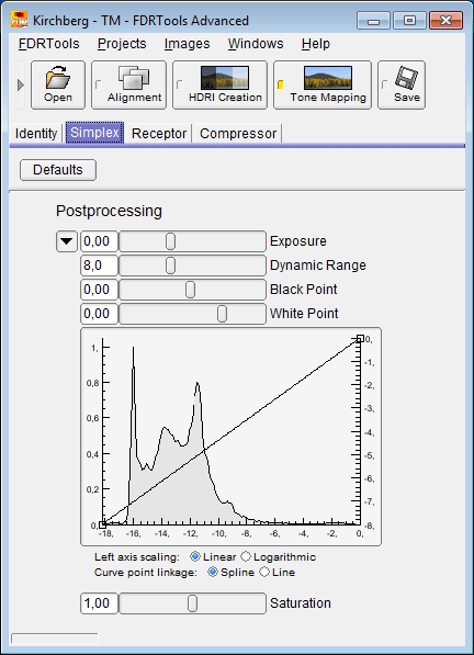
Simplex implements the simplest possible tone mapping algorithm: the HDR image is linearly mapped to the output EV range. Though this method attenuates contrast and details it works fast. It is suited to get an overview of the scene and is useful when editing the HDR image, e.g. with manual alignment.
 |
||
| The Simplex dialog |
The default setting for the curve does the following: the left knot maps the darkest pixel of the tone mapped image to -8 while the right knot maps the brightest pixel to 0. The output values are a measure of the output dynamic range and are in log base 2 units or EV or f-stops. In effect this means that the white point with value 0 has 256 times the luminance of the black point with value -8.
The tone mapped histogram is displayed behind the curve. It is obtained from the luminance channel of the tone mapped image. The histogram is a visual aid for adjusting black point and white point.
Note: the left axis scaling is a measure of the number of entries per histogram bin. It is of informational value only.
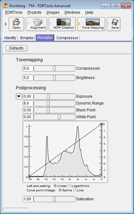
Receptor mapping works by logarithmising the HDR image. The strength of the compression depends on the intensity of a pixel. Highlights are compressed more than shadows.
 |
||
| The Receptor dialog |
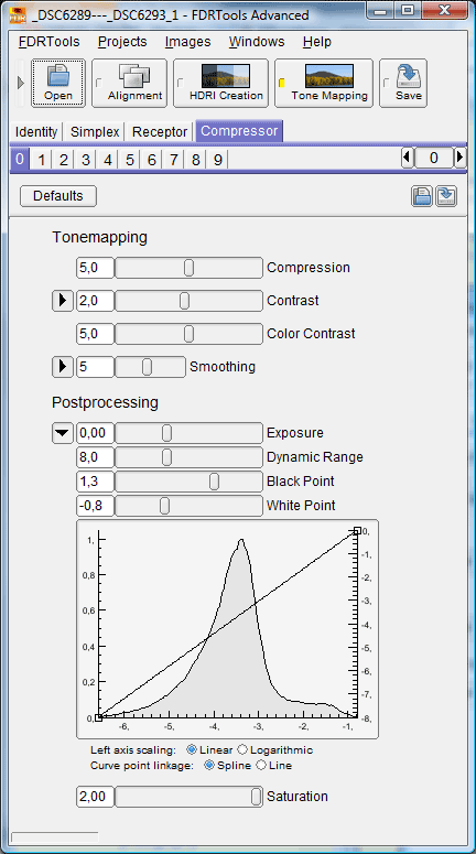
The Compressor algorithm works as follows: the intensity of each pixel is regulated individually and depends on the intensities of neighbouring pixels. If neighbouring pixels differ strongly in their respective intensity, e.g. in the surroundings of a strong light source, then these differences are strongly attenuated. Where the differences are small, e.g. in shadowy areas, there is little or no attenuation, evtl. the difference is even increased. As a result the dynamic range of the HDR image is strongly reduced while local tonal value differences are preserved. Local contrast and thus the perceptibility of details are considerably improved compared to global tone mapping methods like Simplex or Receptor.
Parameter changes are recorded by a history module. The user interface to the history module is a panel placed below the Compressor tab. It consists of ten tabs - the so called "branches" - and a counter with arrowed buttons. Each parameter change increments the counter and the change is saved in the active branch. The arrowed buttons allow to browse the history of the active branch. Selecting a different branch switches to the history of that branch or - if that branch has no history yet - the history is started with the current set of parameters. This way up to ten history branches can be maintained and compared with each other. A history branch can be reset by browsing backwards until the counter shows -1.
 |
||
| The Compressor dialog |
 |
|||
| Compressor Color Contrast |
If you encounter halos in a tone mapped image you can remove them by adjusting the Frequency components of the Contrast parameter.
If you encounter spots in a tone mapped image you can remove them by lowering the Compression parameter value.
Look at the following image comparison. The first image shows the Simplex result. The second image shows the result of using the Compressor default settings. You can here perceive slight halos along the pylons and moreover dark looking spots inside the pylons. The third image results from properly adjusting the Compressor parameters.
 |
|||
| Compressor halos and spots (image by courtesy of Alessandro de Simone) |
How to adjust the Compressor parameters: in general lower the Compression value until the spots disappear but keep it as high as possible in order to achieve good details and contrast. Adjust the Contrast->Frequency curve as shown below (to access the Contrast->Frequency option click the arrow button left to the Contrast slider). Set the 'Curve point linkage' option to 'Line'. The intention is to lower the impact of frequency components that are responsible for the halos.
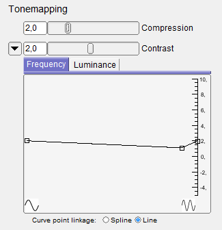 |
|
| The relevant Compressor parameters | |
The following example clarifies the characteristics of the tone mapping algorithms. It is a night scene. Night scenes are especially hard to handle because usually they are high dynamic range and prone to noise. Nearly always there are very dark areas that can hardly be exposed free from noise. Noise is a problem when tone mapping with Compressor. Compressor does not distinguish noisy pixels from "clean" pixels. Therefore noisy pixels gain contrast too and hence gain perceptibility. For this reason the tone mapping example deals not only with tone mapping itself but also with the preparation, namely the creation of a noise-free HDR image.
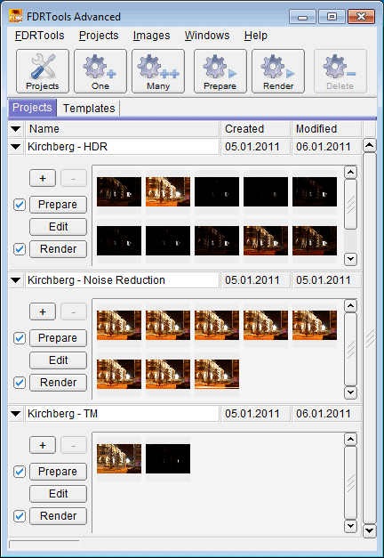 |
||
| Night shot - projects |
The possibly strong noise in night scenes is caused by a low signal-to-noise ratio in very dark image areas like the night sky. Even quite long exposure does not yield a measurable signal because there is simply not enough light - the background noise of the camera electronics prevails. Noise can be fought in several ways. The cleanest way - because image quality is preserved - is the following method. Dark image areas emit light also, albeit very little. In order to get a sufficiently strong signal one has to expose longer. There are two ways to expose for an arbitrary long time:
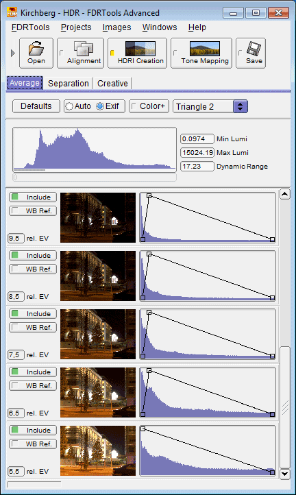 |
||
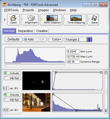
| First part of the project - the HDR image |
The figure to the left shows the first part of the HDR image, an exposure series consisting of 11 exposures with exposure times ranging from 1/100 of a second to 10 seconds. The resulting HDR image is not noise-free. Longer exposure times are realised with a second exposure series, see below.
 |
||
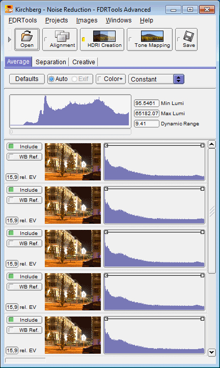
| Second part - long time exposure |
The figure to the left shows the second part of the HDR image. This series comprises 8 photos, each of them exposed for 10 seconds. The 8 images correspond to a single photo with an 80 seconds exposure time. This in turn means a difference of 3 EV or f-stops compared to a single photo. The photos are merged with the HDR method Average. The pixels are weighted using weighting curve "Constant" which means that the resulting value of a pixel is calculated as the sum of the pixel values from all images divided by the number of images.
 |
||
| Third part - the final noise-free HDR image |
The figure to the left shows the third part, the final HDR image, consisting of the HDR images from the two previous projects. The HDR image is nois-free and is tone mapped.
The following figures show the results achieved with the different tone mappers applied to the HDR image. The first figure shows the overview, the second figure a detail of the scene. In order to make the results of the algorithms comparable the intensity of the brightest feature in the scene - an illuminated cage - is adjusted so that the intensity is about the same for all tone mappers. Note that the intention of this example is not to produce the best looking result but to show the differences between the tone mappers.
 |
|||
| Overview |
 |
|||
| Detail |
While the Simplex result is noise-free and does not show overexposed pixels, it is rather dark and shows poor contrast. It is not easy to discern fine detail.
Receptor creates a brighter image. The reason for this is a stronger compression of the highlights and linked to it a spreading of dark and medium tonal values. As a consequence the contrast in the highlights decreases: the reflection of the illuminated cage appears brighter but less detailed compared to Simplex. On the other hand the contrast increases in the lower and medium tonal value ranges.
Compressor yields a well-balanced result. All areas of the scene are sufficiently bright. Even details of the wheelhouse of the car in the front (see the overview image) are recognizable. However, good contrast and hence details are preserved over the full tonal value spectrum. The resulting image looks quite natural.